


The AJ320 flexible joint is designed for use in a variety of general piping applications of moderate or high pressure services.
- Grooved joint for High Pressure and STS
- Grooved joint Flexible type
- Joint material: Spherical graphite cast iron (ASTM A536, GCD450)
- Gasket material: EPDM
- Bolt/nut material: Carbon steel for mechanical structure
- Painting: Epoxy powder painting
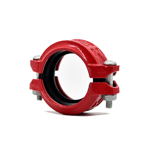
The Model AJ320 Flexible Coupling is designed for use in a variety of general piping applications of moderate or high pressure services.
The Model AJ320 couplings feature flexibility that can accommodate misalignment, distortion, thermal stress, vibration and noise and also resist seismic tremors. The utilization of Model AJ320 couplings can accommodate a curved layout.
The Model AJ320 couplings are comprised of two housing segments, EPDM gaskets and plated track bolts and nuts.
AJ320 couplings should always be installed so that the coupling bolt pads make metal to metal contact.
Material specification
- Housing: Ductile Iron to ASTM A536, Gr. 65-45-12, min. tensile strength 65,000 psi (448 MPa)
- Surface Finish: Epoxy Coating
- Rubber Gasket: Grade EPDM approved under NSF/ANSI 61.
- Bolts & Nut: CS for machine structural use.
[ Product specification ]
| Nominal Size DN Inch |
Pipe O.D. (mm) |
Max. Working Pressure (kgf/cm2) |
Max.End Load(kN) |
Allow. Pipe End Sep(mm) |
Degrees- per Joint |
Pipe Deflection (mm/6m) |
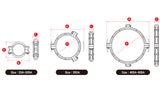
Dimensions (mm) |
Bolt Size (ΦxL) |
Wrench Size (mm) |
Weight (kg) |
||
|---|---|---|---|---|---|---|---|---|---|---|---|---|
| A | B | C | ||||||||||
| 25 1 |
33.7 | 40 | 3.6 | 1.3 | 2.19˚ | 229.33 | 60 | 101.4 | 46.2 | M10 X 50 | 17 | 0.60 |
| 32 1.1/4 |
42.4 | 40 | 5.7 | 1.6 | 2.16˚ | 226.30 | 69 | 103 | 46 | M10 X 60 | 17 | 0.66 |
| 40 1.1/2 |
48.3 | 40 | 7.4 | 1.6 | 1.90˚ | 199.04 | 75 | 108 | 46 | M10 X 60 | 17 | 0.70 |
| 50 2 |
60.3 | 40 | 11.5 | 1.6 | 1.51˚ | 158.16 | 87 | 129 | 47 | M10 X 60 | 17 | 0.80 |
| 65 | 76.1 | 40 | 18.3 | 1.6 | 1.20˚ | 125.68 | 105 | 147 | 47 | M10 X 60 | 17 | 0.90 |
| 2.1/2 | 73.0 | 40 | 18.3 | 1.6 | 1.20˚ | 125.68 | 105 | 147 | 47 | M10 X 60 | 17 | 0.90 |
| 80 3 |
88.9 | 40 | 24.9 | 1.6 | 1.03˚ | 107.87 | 118 | 164 | 47 | M12 X 75 | 19 | 1.38 |
| 100 4 |
114.3 | 40 | 41.0 | 3.2 | 1.60˚ | 167.60 | 149 | 197 | 51 | M12 X 75 | 19 | 2.02 |
| 125 | 139.7 | 36 | 55.2 | 3.2 | 1.31˚ | 137.21 | 176 | 248 | 52 | M16 X 95 | 24 | 2.92 |
| 5 | 141.3 | 36 | 55.2 | 3.2 | 1.31˚ | 137.21 | 176 | 248 | 52 | M16 X 95 | 24 | 2.92 |
| 150 | 165.1 | 36 | 77.2 | 3.2 | 1.11˚ | 116.25 | 200 | 265 | 52 | M16 X 95 | 24 | 3.02 |
| 6 | 168.3 | 36 | 77.2 | 3.2 | 1.11˚ | 116.25 | 200 | 265 | 52 | M16 X 95 | 24 | 3.02 |
| 200 | 216.3 | 30 | 110.2 | 3.2 | 1.83˚ | 191.70 | 260 | 350 | 61 | M20 X 120 | 30 | 5.90 |
| 8 | 219.1 | 30 | 110.2 | 3.2 | 1.83˚ | 191.70 | 260 | 350 | 61 | M20 X 120 | 30 | 5.90 |
| 250 | 267.4 | 30 | 168.5 | 3.2 | 1.33˚ | 139.30 | 312 | 402 | 66 | M20 X 120 | 30 | 11.80 |
| 10 | 273.0 | 30 | 168.5 | 3.2 | 1.33˚ | 139.30 | 312 | 402 | 66 | M20 X 120 | 30 | 11.80 |
| 300 | 318.5 | 30 | 239.0 | 3.2 | 1.13˚ | 118.35 | 363 | 460 | 66 | M22 X 155 | 32 | 14.50 |
| 12 | 323.9 | 30 | 239.0 | 3.2 | 1.13˚ | 118.35 | 363 | 460 | 66 | M22 X 155 | 32 | 14.50 |
| 350 14 |
355.6 | 25 | 248.3 | 3.2 | 1.03˚ | 107.87 | 416 | 507 | 75 | M22 X 115 | 32 | 15.24 |
| 400 16 |
406.4 | 25 | 324.3 | 3.2 | 0.90˚ | 94.26 | 468 | 561 | 76 | M24 X 125 | 32 | 19.18 |
| 450 18 |
457.2 | 25 | 410.4 | 3.2 | 0.80˚ | 83.78 | 520 | 614 | 78 | M24 X 125 | 32 | 21.40 |
| 500 20 |
508.0 | 20 | 405.4 | 3.2 | 0.71˚ | 74.35 | 574 | 684 | 78 | M24 X 125 | 32 | 25.02 |
| 600 24 |
610.0 | 20 | 583.7 | 3.2 | 0.60˚ | 62.83 | 677 | 786 | 79 | M24 X 125 | 32 | 30.14 |
※ The dimensions and Data values in the table above are subject to change to improve performance.
※ Please contact us for other sizes.
[General note]
*Maximum Working Pressure (CWP) listed is the maximum cold water pressure for general piping services tested to UL213.
*Please always refer to the latest approval data posted on the NEWASIA website.
*Warning: Piping systems must always be depressurized and drained before attempting disassembly and or removal of any components.
*The 2 Year Limited Warranty applies to manufacturing defects only and does not cover severe service/temperature applications or wear parts.
*NEWASIA reserves the right to change specifications, designs and or standard without notice and without incurring any obligations.
New Asia One-Stop grooved Joint Product Introduction Video
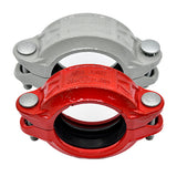
New Asia One-Stop grooved Joint vs General grooved Joint Construction Comparison 01
New Asia One-Stop grooved Joint vs General grooved Joint Construction Comparison 02


- Choosing a selection results in a full page refresh.