


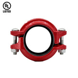
The AJ520 rigid joint is designed with a diagonal slide method to provide a solid connection. It is is easy to join high-pressure pipes.
- Grooved joint for High Pressure and STS
- Grooved joint Rigid type
- Joint material: Spherical graphite cast iron (ASTM A536, GCD450)
- Gasket material: EPDM
- Bolt/nut material: Carbon steel for mechanical structure
- Painting: Epoxy powder painting
The Model AJ520 is an angle-pad design rigid coupling for general piping applications where rigidity is required including valve connections, mechanical rooms, fire mains and long straight runs. The angle-pad design allows the coupling housings to slide along the bolt pads when tightened. The result is an offset clamping action which provides a rigid joint that resists flexural and torsional loads.
AJ520 couplings should always be installed so that the coupling bolt pads make metal to metal contact
Material specification
- Housing: Ductile Iron to ASTM A536, Gr. 65-45-12, min. tensile strength 65,000 psi (448 MPa)
- Surface Finish: Epoxy Coating
- Rubber Gasket: Grade EPDM approved under NSF/ANSI 61.
- Bolts & Nut: CS for machine structural use.
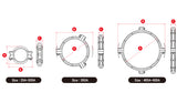
[ Product specification ]
| Nominal Size DN Inch |
Pipe O.D. (mm) |
Max. Working Pressure (kgf/cm2) |
Max.End Load (kN) |
Allow. Pipe End Sep (mm) |
Dimensions (mm) |
Bolt Size (ΦxL) |
Wrench Size (mm) |
Weight (kg) |
||
|---|---|---|---|---|---|---|---|---|---|---|
| A | B | C | ||||||||
| 40 1.1/2 |
48.3 | 52 | 9.7 | 1.1 | 76 | 113 | 48 | M10 X 60 | 17 | 0.88 |
| 50 2 |
60.3 | 52 | 15.0 | 1.6 | 87 | 123 | 50 | M10 X 70 | 17 | 1.06 |
| 65 | 76.1 | 52 | 23.8 | 1.6 | 103 | 142 | 51 | M10 X 70 | 17 | 1.30 |
| 2.1/2 | 73.0 | 52 | 23.8 | 1.6 | 103 | 142 | 51 | M10 X 70 | 17 | 1.30 |
| 80 3 |
88.9 | 52 | 32.4 | 1.6 | 116 | 170 | 51 | M12 X 75 | 19 | 1.68 |
| 100 4 |
114.3 | 52 | 53.4 | 2.9 | 148 | 202 | 55 | M12 X 75 | 19 | 2.16 |
| 125 | 139.7 | 48 | 73.6 | 2.9 | 174 | 242 | 55 | M16 X 95 | 24 | 3.00 |
| 5 | 141.3 | 48 | 73.6 | 2.9 | 174 | 242 | 55 | M16 X 95 | 24 | 3.00 |
| 150 | 165.1 | 48 | 102.9 | 2.9 | 200 | 269 | 56 | M16 X 95 | 24 | 3.50 |
| 6 | 168.3 | 48 | 102.9 | 2.9 | 200 | 269 | 56 | M16 X 95 | 24 | 3.50 |
| 200 | 216.3 | 41 | 150.7 | 3.2 | 261 | 341 | 65 | M20 X 120 | 30 | 6.80 |
| 8 | 219.1 | 41 | 150.7 | 3.2 | 261 | 341 | 65 | M20 X 120 | 30 | 6.80 |
| 250 | 267.4 | 34 | 190.9 | 3.2 | 315 | 399 | 66 | M20 X 120 | 30 | 8.82 |
| 10 | 273.0 | 34 | 190.9 | 3.2 | 315 | 399 | 66 | M20 X 120 | 30 | 8.82 |
| 300 | 318.5 | 27 | 215.1 | 3.2 | 370 | 468 | 67 | M22 X 160 | 32 | 12.68 |
| 12 | 323.9 | 27 | 215.1 | 3.2 | 370 | 468 | 67 | M22 X 160 | 32 | 12.68 |
| 350 14 |
355.6 | 17 | 168.8 | 3.2 | 413 | 513 | 73 | M22 X 130 | 32 | 16.64 |
| 400 16 |
406.4 | 17 | 220.5 | 3.2 | 465 | 563 | 73 | M22 X 130 | 32 | 18.66 |
| 450 18 |
457.2 | 17 | 279.1 | 2.6 | 519 | 616 | 76 | M24 X 140 | 32 | 19.28 |
| 500 20 |
508.0 | 17 | 344.6 | 3.3 | 573 | 686 | 78 | M24 X 140 | 32 | 26.82 |
| 600 24 |
610.0 | 17 | 496.2 | 3.3 | 673 | 787 | 79 | M24 X 140 | 32 | 32.04 |
※ The dimensions and Data values in the table above are subject to change to improve performance.
※ Please contact us for other sizes.
[General note]
*Maximum Working Pressure (CWP) listed is the maximum cold water pressure for general piping services tested to UL213.
*Please always refer to the latest approval data posted on the NEWASIA website.
*Warning: Piping systems must always be depressurized and drained before attempting disassembly and or removal of any components.
*The 2 Year Limited Warranty applies to manufacturing defects only and does not cover severe service/temperature applications or wear parts.
*NEWASIA reserves the right to change specifications, designs and or standard without notice and without incurring any obligations.
New Asia One-Stop grooved Joint Product Introduction Video
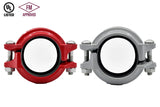
New Asia One-Stop grooved Joint vs General grooved Joint Construction Comparison 01
New Asia One-Stop grooved Joint vs General grooved Joint Construction Comparison 02


- Choosing a selection results in a full page refresh.