
The grooved joint method is simpler and faster than welding in the field. To relieve the stress of the piping, change the orientation of the piping or use the joint to secure the piping.
- Industrial standard: KS, JIS, ANSI
- Grooved Outlet type
- Joint material: Spherical graphite cast iron(ASTM A536, GCD450)
- Gasket Material: EPDM
- Bolt/nut material: Carbon steel for mechanical structures
- Painting: Epoxy Powder Painting
The grooved joint method is simpler and faster than welding in the field.
To relieve the stress of the piping, change the orientation of the piping or use the joint to secure the piping.
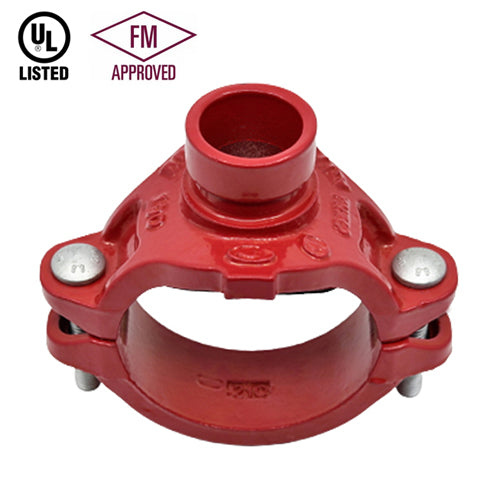
The Model AJS720G Outlet Coupling combines the features of a coupling and a reducing outlet. The AJS720G is a joining device with an integral reducing outlet, eliminating the need for a mechanical tee or a reducing tee and couplings. The AJS720G 1s available with grooved, male threaded or female threaded outlets. The AJS720G coupling is recommended for fire sprinkler services and other applications up to 300 psi (20 Bar) depending on the size and schedule of pipe being used. All Model AJS720G couplings are comprised of an upper and lower ductile iron housings segment, EPDM rubber gasket and plated track bolts & nuts.
AJS720G couplings should always be installed so that the coupling bolt pads make metal to metal contact.
Material specification
- Housing: Ductile Iron to ASTM A536, Gr. 65-45-12, min. tensile strength 65,000 psi (448 MPa).
- Surface Finish: Epoxy Coating
- Rubber Gasket: Grade EPDM approved under NSF/ANSI 61.
- Bolts & Nut: CS for machine structural use.
[ Product specification ]
| Nominal Size (A) |
Pipe O.D (mm) |
Max. Working Pressure (kgf/cm2) |
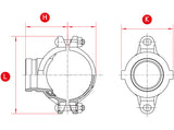
Dimensions (mm) |
Bolt Size (ф x L) |
Wrench Size (mm) |
Hole Dia (mm) |
|||
|---|---|---|---|---|---|---|---|---|---|
| L | K | H | |||||||
| 50A | 32A | 60.3x42.4 | 21 | 116 | 75 | 66 | M10x55 | 15 | 51 |
| 40A | 60.3x48.3 | 21 | 116 | 75 | 66 | M10x55 | 15 | 51 | |
| 65A | 32A | 76.1x42.4 | 21 | 128 | 84 | 78 | M10x60 | 15 | 51 |
| 40A | 76.1x48.3 | 21 | 128 | 84 | 78 | M10x60 | 15 | 51 | |
| 80A | 32A | 88.9x42.4 | 21 | 151 | 86 | 80 | M12x65 | 19 | 51 |
| 40A | 88.9x48.3 | 21 | 151 | 86 | 80 | M12x65 | 19 | 51 | |
| 50A | 88.9x60.3 | 21 | 151 | 101 | 80 | M12x65 | 19 | 64 | |
| 100A | 40A | 114.3x48.3 | 21 | 183 | 88 | 100 | M12x75 | 19 | 51 |
| 50A | 114.3x60.3 | 21 | 183 | 105 | 100 | M12x75 | 19 | 64 | |
| 65A | 114.3x76.1 | 21 | 183 | 110 | 100 | M12x75 | 19 | 70 | |
| 125A | 40A | 139.7x48.3 | 21 | 219 | 92 | 110 | M16x80 | 24 | 51 |
| 50A | 139.7x60.3 | 21 | 219 | 105 | 110 | M16x80 | 24 | 64 | |
| 65A | 139.7x76.1 | 21 | 219 | 110 | 110 | M16x80 | 24 | 70 | |
| 80A | 139.7x88.9 | 21 | 219 | 124 | 110 | M16x80 | 24 | 89 | |
| 150A | 50A | 165.1x60.3 | 21 | 245 | 105 | 123 | M16x90 | 24 | 64 |
| 65A | 165.1x76.1 | 21 | 245 | 110 | 123 | M16x90 | 24 | 70 | |
| 80A | 165.1x88.9 | 21 | 245 | 130 | 123 | M16x90 | 24 | 89 | |
| 100A | 165.1x114.3 | 21 | 245 | 159 | 125 | M16x90 | 24 | 114 | |
| Nominal Size (A) |
Pipe O.D (mm) |
Max. Working Pressure (kgf/cm2) |
Dimensions (mm) |
Bolt Size (ф x L) |
Wrench Size (mm) |
Hole Dia (mm) |
|||
|---|---|---|---|---|---|---|---|---|---|
| L | K | H | |||||||
| 2" | 1-1/4" | 60.3x42.4 | 21 | 116 | 75 | 66 | M10x55 | 15 | 51 |
| 1-1/2" | 60.3x48.3 | 21 | 116 | 75 | 66 | M10x55 | 15 | 51 | |
| 2-1/2" | 1-1/4" | 73.0x42.4 | 21 | 128 | 84 | 78 | M10x60 | 15 | 51 |
| 1-1/2" | 73.0x48.3 | 21 | 128 | 84 | 78 | M10x60 | 15 | 51 | |
| 3" | 1-1/4" | 88.9x42.4 | 21 | 151 | 86 | 80 | M12x65 | 19 | 51 |
| 1-1/2" | 88.9x48.3 | 21 | 151 | 86 | 80 | M12x65 | 19 | 51 | |
| 2" | 88.9x60.3 | 21 | 151 | 101 | 80 | M12x65 | 19 | 64 | |
| 4" | 1" | 114.3x33.7 | 21 | 183 | 76 | 96 | M12x75 | 19 | 38 |
| 1-1/4" | 114.3x42.4 | 21 | 183 | 88 | 100 | M12x75 | 19 | 51 | |
| 1-1/2" | 114.3x48.3 | 21 | 183 | 88 | 100 | M12x75 | 19 | 51 | |
| 2" | 114.3x60.3 | 21 | 183 | 105 | 100 | M12x75 | 19 | 64 | |
| 2-1/2" | 114.3x73.0 | 21 | 183 | 110 | 100 | M12x75 | 19 | 70 | |
| 3" | 114.3x88.9 | 21 | 183 | 125 | 100 | M12x75 | 19 | 89 | |
| 5" | 1-1/4" | 141.3x42.4 | 21 | 219 | 92 | 110 | M16x80 | 24 | 51 |
| 1-1/2" | 141.3x48.3 | 21 | 219 | 92 | 110 | M16x80 | 24 | 51 | |
| 2" | 141.3x60.3 | 21 | 219 | 105 | 110 | M16x80 | 24 | 64 | |
| 6" | 1-1/4" | 168.3x42.4 | 21 | 250 | 90 | 127 | M16x90 | 24 | 51 |
| 1-1/2" | 168.3x48.3 | 21 | 250 | 90 | 127 | M16x90 | 24 | 51 | |
| 2" | 168.3x60.3 | 21 | 250 | 105 | 127 | M16x90 | 24 | 64 | |
| 2-1/2" | 168.3x73.0 | 21 | 250 | 110 | 127 | M16x90 | 24 | 70 | |
| 3" | 168.3x88.9 | 21 | 250 | 130 | 127 | M16x90 | 24 | 89 | |
| 4" | 168.3x114.3 | 21 | 250 | 159 | 127 | M16x90 | 24 | 114 | |
※ The dimensions and Data values in the table above are subject to change to improve performance.
※ Please contact us for other sizes.
[General note]
*Maximum Working Pressure (CWP) listed is the maximum cold water pressure for general piping services tested to UL213.
*Please always refer to the latest approval data posted on the NEWASIA website.
*Warning: Piping systems must always be depressurized and drained before attempting disassembly and or removal of any components.
*The 2 Year Limited Warranty applies to manufacturing defects only and does not cover severe service/temperature applications or wear parts.
*NEWASIA reserves the right to change specifications, designs and or standard without notice and without incurring any obligations.
New Asia One-Stop grooved Joint Product Introduction Video
New Asia One-Stop grooved Joint vs General grooved Joint Construction Comparison 01
New Asia One-Stop grooved Joint vs General grooved Joint Construction Comparison 02


- Choosing a selection results in a full page refresh.